
Each electrical engineer needs the right equipment in their lab, and over time the need for specialized equipment increases depending on the project one is working on. Even so, a lot of equipment is suitable for multiple projects. One such device will be discussed in the following article.
I have been working on one larger project (TCS Digital command station) for a long time, and one of my main conditions is to make a perfect device that meets the requirements of the majority of users. Therefore, this device must be sufficiently tested. One of the many tests is the load test and tests against overload and short circuit of the output signal. This is best tested with an Electronic Adjustable Load. Unfortunately, one cannot usually afford to have expensive equipment at home, so I decided to use something from China to start with.
So I ordered the following module (Fig. 1), which is not complete and needs to be supplemented with a few things.
https://www.aliexpress.com/item/75W-Constant-Current-Electronic-Load-100V-6-6A-Battery-Discharge-Capacity-Tester/32707669154.html
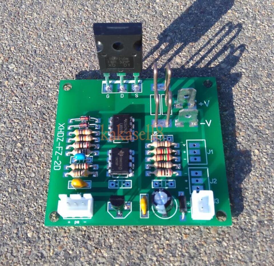
In the description it is written that the load can be connected up to a voltage of 100V and the maximum current can handle 6.6A. It seems incredible to me and unfortunately I haven’t verified these highs myself yet.
After this board arrived, I needed to add a potentiometer (I chose 10K) and also a proper heatsink. I found a cooler from the CPU at home and mounted it on the transistor. For a long time I used the device as a “bastl”, wires were sticking out of it, but it served its purpose. Now it’s time to improve it a little, put it in a box and thus speed up and simplify the work again.
Connection description
So let’s start with how to wire it all up. The seller supplies the device with a diagram (Fig. 2).
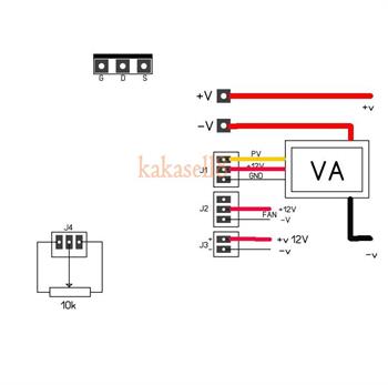
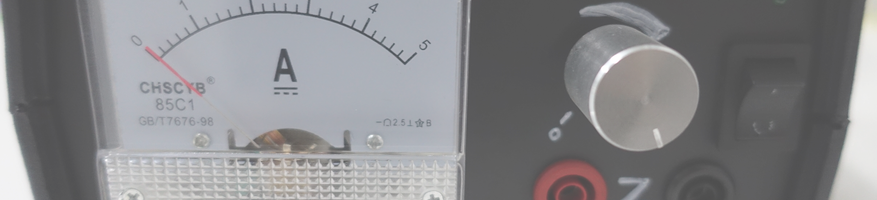
The diagram shows where to connect what. A potentiometer is connected to the lower left – a cable and a connector were included in the package. The package also included a cable with a power connector (J3 connector). Next, I connected the fan to connector J2. Fortunately, the fan connector from the computer’s processor sat right there. And finally, connect the load using fastons (not included in the package) to the terminals marked +V and -V. The diagram also shows how to connect the current and voltage measurements, but I did it a little differently. I bought a needle current meter in China and connected it in series to the terminals with the load (as indicated by the thick red and then black wire). I did not connect to connector J1. I found it the easiest.
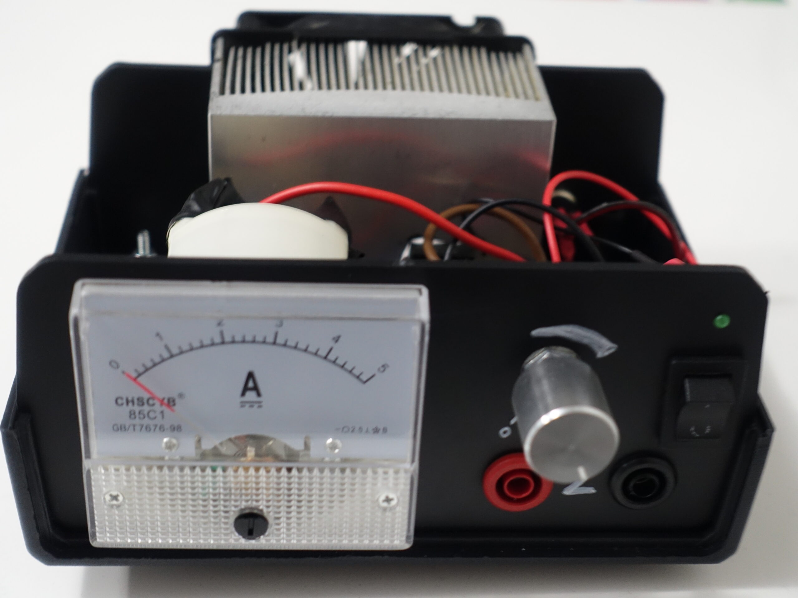
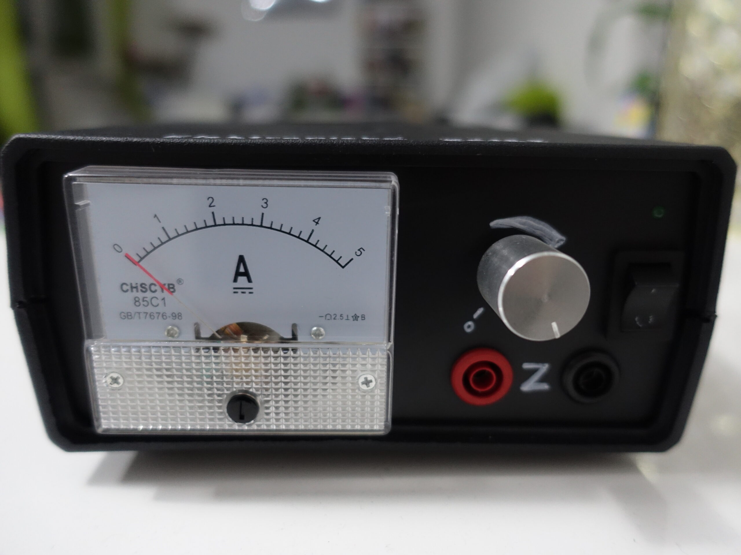
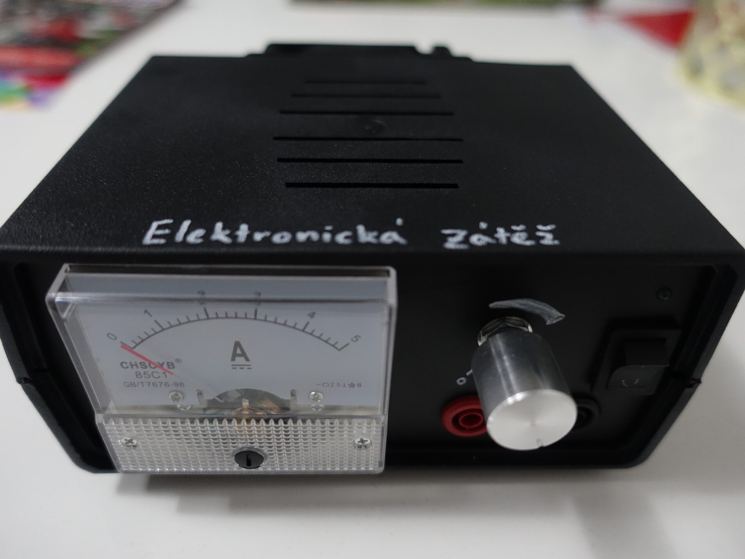
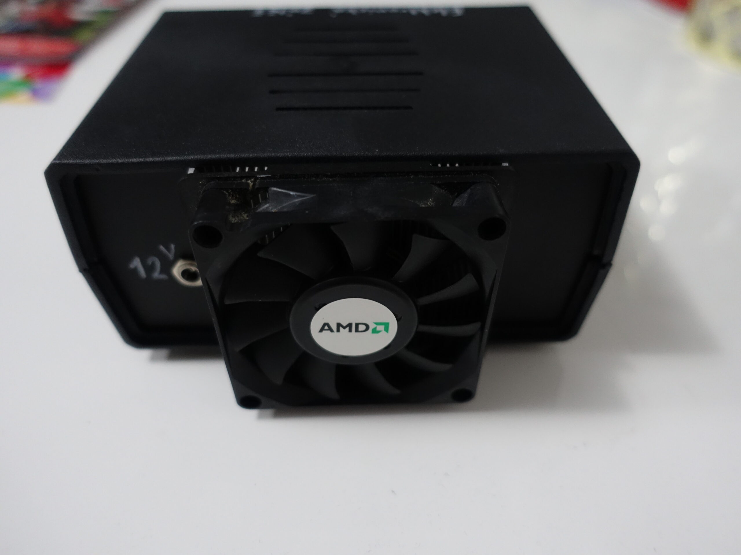
Box
In order to prevent careless handling, short circuits or other inconveniences, I put the entire device in a box. It also speeds up the work quite a bit if I just take the box and plug it in, rather than looking for a free space on the table for some mess of wires. The resulting product can be seen in the photos below.


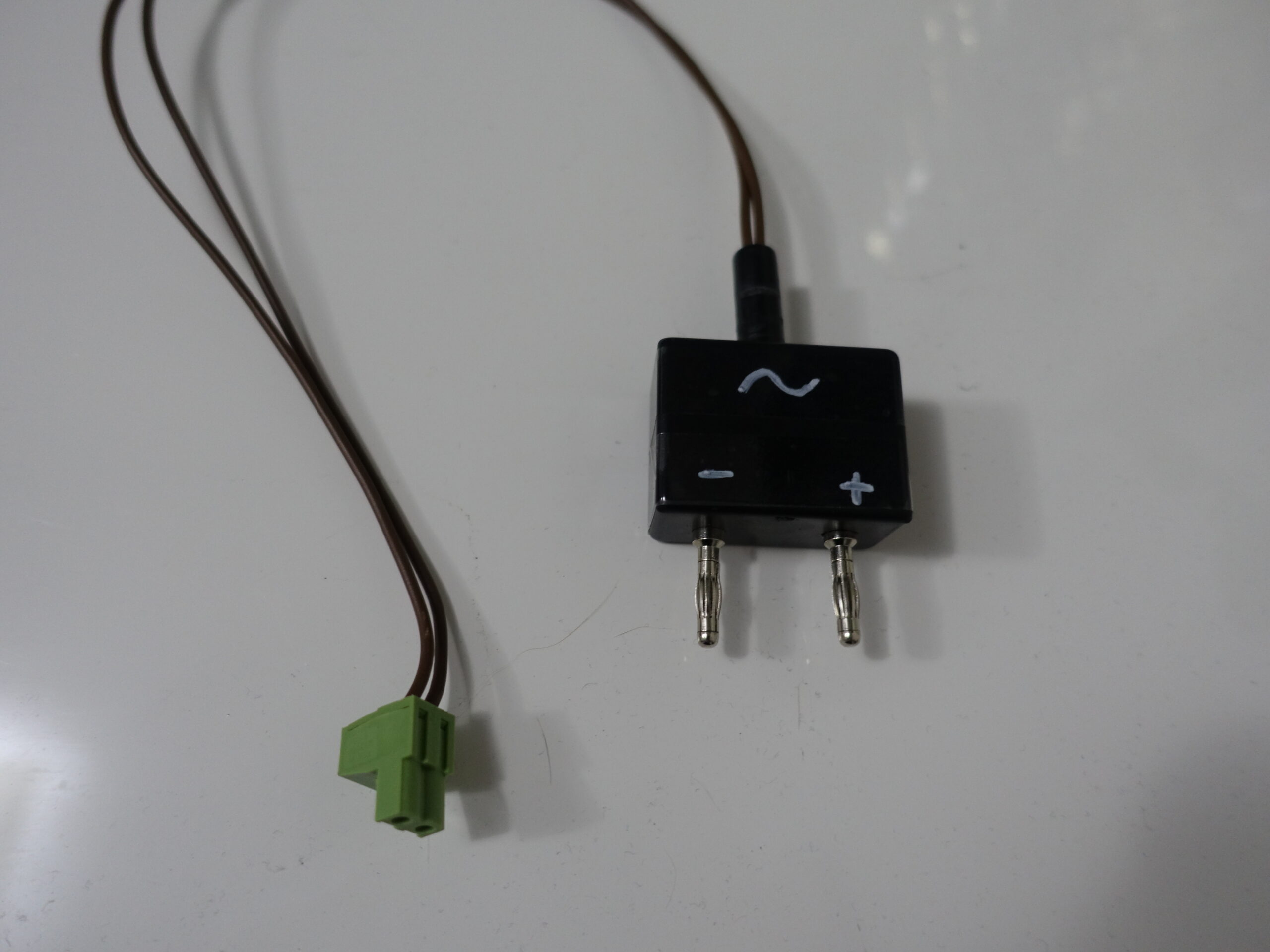
Example of the usage
In the TCS Digital command station project, which I mentioned above, I need to load the output signal, which is alternating current, and measure the current at which the short-circuit protection switches on. In order to be able to do this, I rectified the AC signal and only then connected it to the load. I made a fixture for this – see Figure 3 (below). The output signal is a rectangular AC signal with a maximum output voltage of 18V and the current fuse should switch at 2A. I tried loading up to 4A at 15V. The cooler cooled the load without any problem.