

Have you ever need see the data on your digital model railroad? Or do you only want see the packets of DCC? Now, it is possible with low price or for free!
During the making DCC command station (TCS-2), I wanted see the DCC packets and signals.
At first I was using the logic analyzer from SALEAE, but parsing the all DCC packets was really annoying. I decided make own analyzer for the DCC commands with AVR microcontroller Atmega328. I used board from Arduino Nano, but it was programmed in AVR Studio.
The program is very simple. It is only parsing the all DCC data from rails and writting this data into console. You can see parsed address, type of DCC command, speed of train, direction of train, etc…
The DCC data are writting into console on PC (fig. 1).
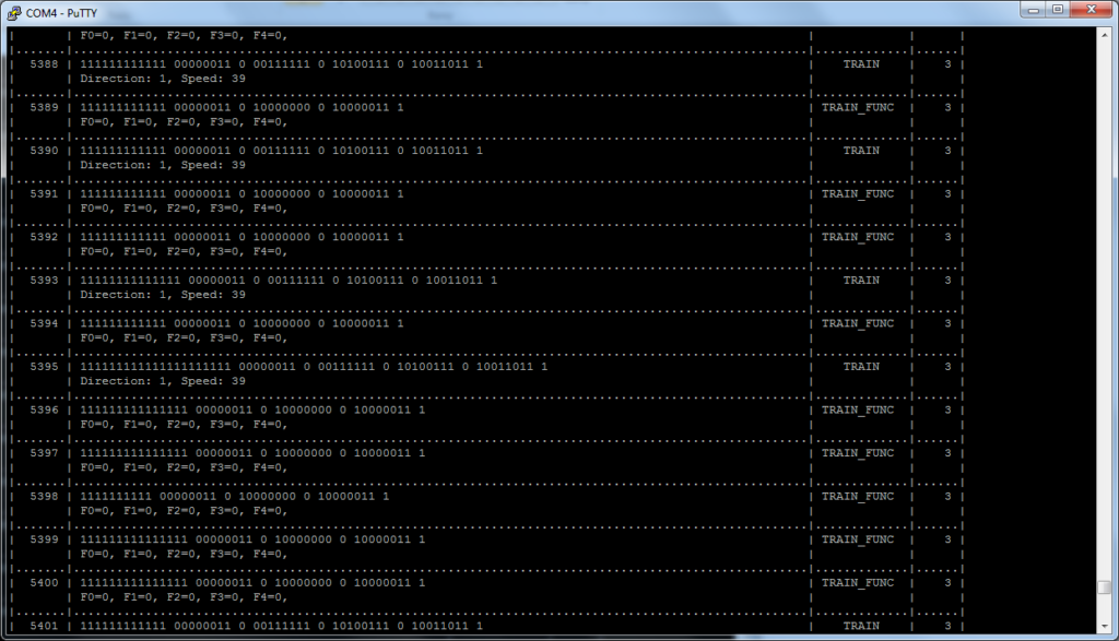
Now, the program can parse these commands:
- IDLE – not active packet, it is for making voltage in rails
- RESET – reset all DCC devices
- TRAIN – control train
- TRAIN_FUNC – train functions (lights, sounds, etc.)
- ACCESSORY – control accessories (lights, turnouts, etc.)
- ACCESSOR_EX – extended accessory packet
- PROGRAM – programming
How can you make it?
It is very simple. You need only Arduino Nano and write the HEX file (download on the end of this article) into it. You will need ISP, ASP or similar programmer.
Then, you make device on schematic (Figure 2). Put the DCC signal to DCC-IN. Connector OUT is used for connection to Arduino (1 – VCC (3V3), 2 – Signal to PB3, 3 – GND)

At the end, we can put all into nice box. (like on the gallery on the ond of article)
After you make the hardware , you can connect device via micro USB from Arduino to USB at computer. You will see new virtual serial port COM on your computer. You can check it on your Device manager (right click to Computer icon -> Properties -> on the left top corner Device manager). Now you should see window like on the picture 3. You will need a number of COM port. You can find out it, when you unplug and plug board into USB port.

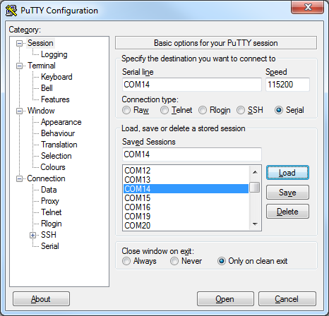
The next step is launch terminal (some the console application). I am using PUTTY (http://www.putty.org/). After you launch the Putty, then you should set right COM port number and baud speed, which is 115 200. You can see the right settings of Putty on the picture 4. Then you click on Open. After that, you should see window like on the picture 2. It should resize the window for better display a table.
Use
You can change display of IDLE packets on the window by press button “i” on your keyboard.
Video
Gallery


Download
You can download the source code on GitHub: https://github.com/zavovi/DCCSniffer
Related posts
 Cheap and the best point machine
 Testing trains with DCC Piko Digi 1
 Trains on the new bridge
 Testing trains on train station – controlled by smartphone with Android
 Testing new features of DCC command station controlled by smartphone with Android application
 Control lights and brightness of the London model house H0
 Digital control of train and turnouts on my model railroads controlled by Android application
 New train model – ČSD T478.1
 Model of the bus KAROSA B-931 DPMB Brno in H0